


Function: Prevents discharge of separated oil to sewer/streams
Large, unpredictable oil and fuel spills can defeat the most conservatively designed pollution control system. But while the cost of redesigning such a system can be prohibitive, the consequences of not controlling a spill can be equally catastrophic. The AFL Oil Stop Valve (OSV) is designed to economically solve these problems by confining even large oil spills to the premises. Oil Stop Valves can be used as part of your compliance plan to meet requirements of the EPA’s Spill Prevention, Control and Countermeasure regulations.
More information regarding the SPCC >
REQUEST A QUOTEThe AFL Oil Stop Valve is fabricated from non-corrosive PVC or stainless steel. Standard sizes are 4”, 6” 8”, 10” and 12” discharge piping. Larger piping systems can be accommodated by manifolding units together. Optional screening can be provided if necessary to prevent the discharge of large floating solids. An optional slave valve is recommended if evaporation or leaky manholes allow the main float to close. Once rainwater enters the manhole, the slave valve will open and equalize the pressure allowing the main float to reopen.
The OSV is designed for easy installation to any existing separators, catch basins or manholes. AFL also provides the OSV prepackaged in a fiberglass or concrete catch basin or as an option on AFL’s oil water separators. Consider the OSV for those applications where oil spills are possible, but unpredictable such as electrical transformers, oil storage areas, and transportation fueling systems. The Oil Stop Valve is the most cost effective method to prevent a major disaster.
AFL Oil Stop Valves can be used as part of your compliance plan to meet requirements of EPA 40CFR112 SPCC- Spill Prevention, Control, and Countermeasure. Click here for more information regarding the SPCC
Chapter 3 of the EPA’s SPCC guidance for regional inspectors discusses the use of alternative technologies that provide environmental protection equivalency to a manually operated valve. Click here to access the EPA SPCC GUIDANCE FOR REGIONAL INSPECTORS. (PDF , 921pgs)
NOTE: The EPA requires that the facility or facility operator must have a documented plan for compliance to the SPCC approved by a professional engineer.
The OSV in Action:
The OSV has only one mechanical moving part, a ballasted float set at a specific gravity between that of oil and water (.95 or less). When an oil spill occurs, the float loses buoyancy as the oil level increases until it finally seats itself on the discharge port. Thus the oil spill is confined.
CHOOSING THE PROPER VALVE TYPE AND MATERIAL
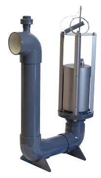
PVC
PVC models are the most economical way to prevent bulk hydrocarbon spills.
Corrosion resistant PVC construction is an ideal choice for warm climates.
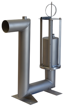
Stainless Steel Not Extended
Used in lieu of PVC units in colder climates, which may eliminate the necessity for an electric freeze protection package.
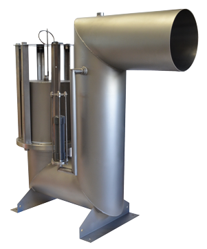
Stainless Steel Extended
The best option if fire is possible. By extending the pipe thru the sump wall, there is no connection inside the sump to burn and fail.
Chapter 3 of the EPA’s SPCC guidance for regional inspectors discusses the use of alternative technologies that provide environmental protection equivalency to a manually operated valve. Click here to access the EPA SPCC GUIDANCE FOR REGIONAL INSPECTORS. (PDF , 921pgs)
NOTE: The EPA requires that the facility or facility operator must have a documented plan for compliance to the SPCC approved by a professional engineer.
| TYPE | MODEL # | SIZE | VALVE MATERIAL | (MIN) DEPTH BELOW OUTLET INVERT | MAX. FLOW RATE* | |||
|---|---|---|---|---|---|---|---|---|
| in. | mm | ft | mm | GPM | L/m | |||
| STANDARD | OSV-4SS | 4″ | 101 mm | STAINLESS STEEL | 2’-3” | 686 | 160 | 606 |
| OSV-6SS | 6″ | 152 mm | STAINLESS STEEL | 2’-6” | 762 | 360 | 1362 | |
| OSV-8SS | 8″ | 203 mm | STAINLESS STEEL | 2’-10 1/2″ | 876 | 600 | 2274 | |
| OSV-10SS | 10″ | 254 mm | STAINLESS STEEL | 3’-1” | 940 | 900 | 3408 | |
| OSV-12SS | 12″ | 304 mm | STAINLESS STEEL | 3’-5” | 1042 | 1400 | 5298 | |
| OSV-4 | 4″ | 101 mm | PVC | 2’-3” | 686 | 160 | 606 | |
| OSV-6 | 6″ | 152 mm | PVC | 2’-6” | 762 | 360 | 1362 | |
| OSV-8 | 8″ | 203 mm | PVC | 2’-10 1/2” | 876 | 600 | 2274 | |
| EXTENDED | OSV-4SST | 4″ | 101 mm | STAINLESS STEEL | 2’-3” | 686 | 160 | 606 |
| OSV-6SST | 6″ | 152 mm | STAINLESS STEEL | 2’-6” | 762 | 360 | 1362 | |
| OSV-8SST | 8″ | 203 mm | STAINLESS STEEL | 2’-10 1/2” | 876 | 600 | 2274 | |
| OSV-10SST | 10″ | 254 mm | STAINLESS STEEL | 3’-1” | 940 | 900 | 3408 | |
| OSV-12SST | 12″ | 304 mm | STAINLESS STEEL | 3’-5” | 1042 | 1400 | 5298 | |
| STANDARD W/ SLAVE VALVE | OSV-4SSSV | 4″ | 101 mm | STAINLESS STEEL | 2’-3” | 686 | 160 | 606 |
| OSV-6SSSV | 6″ | 152 mm | STAINLESS STEEL | 2’-6” | 762 | 360 | 1362 | |
| OSV-8SSSV | 8″ | 203 mm | STAINLESS STEEL | 2’-10 1/2” | 876 | 600 | 2274 | |
| OSV-10SSSV | 10″ | 254 mm | STAINLESS STEEL | 3’-1” | 940 | 900 | 3408 | |
| OSV-12SSSV | 12″ | 304 mm | STAINLESS STEEL | 3’-5” | 1042 | 1400 | 5298 | |
| OSV-4SV | 4″ | 101 mm | PVC | 2’-3” | 686 | 160 | 606 | |
| OSV-6SV | 6″ | 152 mm | PVC | 2’-6” | 762 | 360 | 1362 | |
| OSV-8SV | 8″ | 203 mm | PVC | 2’-10 1/2” | 876 | 600 | 2274 | |
| EXTENDED W/ SLAVE VALVE | OSV-4SSTSV | 4″ | 101 mm | STAINLESS STEEL | 2’-3” | 686 | 160 | 606 |
| OSV-6SSTSV | 6″ | 152 mm | STAINLESS STEEL | 2’-6” | 762 | 360 | 1362 | |
| OSV-8SSTSV | 8″ | 203 mm | STAINLESS STEEL | 2’-10 1/2” | 876 | 600 | 2274 | |
| OSV-10SSTSV | 10″ | 254 mm | STAINLESS STEEL | 3’-1” | 940 | 900 | 3408 | |
| OSV-12SSTSV | 12″ | 304 mm | STAINLESS STEEL | 3’-5” | 1042 | 1400 | 5298 | |
| *WARNING: EXCEEDING THESE FLOW RATES MAY CAUSE PREMATURE CLOSURE | ||||||||


